

Introduction
Modern robotics relies on one critical foundation: the robot control system. Whether engineers deploy autonomous mobile robots in warehouses, six-axis robotic arms in automotive plants, or collaborative robots on production lines, performance ultimately depends on how well the control system manages precision, speed, and safety.
This system acts as the robot’s brain and nervous system. It receives commands, processes sensor data, calculates motion trajectories, and continuously adjusts actuator outputs to achieve precise movement. As industrial automation evolves, engineers must balance processing power, communication latency, real-time responsiveness, and control stability to achieve optimal performance.
This guide explores robot controller architecture, industrial robot programming and control strategies, hardware selection, ROS 2 integration, real-world latency troubleshooting, and advanced control loop optimization techniques.
What Is a Robot Control System?
A robot control system consists of hardware and software components that govern robotic behavior. It receives commands, processes sensor information, generates motion trajectories, and sends instructions to actuators.
The controller continuously evaluates the robot’s current state and compares it against desired outcomes. When deviations occur, the system adjusts motor commands to minimize errors.
Core responsibilities include:
- Motion planning
- Sensor data processing
- Actuator control
- Path optimization
- Safety monitoring
- Real-time decision-making
Communication management. Without these capabilities, robotic systems would operate blindly and fail to achieve precise positioning or repeatability.
Open-Loop vs. Closed-Loop: The Feedback Crux
Control engineers typically choose between open-loop and closed-loop architectures.

| Feature | Open-Loop Control | Closed-Loop Control |
| Feedback | No | Yes |
| Accuracy | Lower | Higher |
| Cost | Lower | Higher |
| Error Correction | None | Continuous |
| Industrial Use | Limited | Extensive |
| Reliability | Moderate | High |
Open-loop systems send commands without verifying the results. A stepper motor operating without feedback represents a common example.
Closed-loop systems continuously compare actual performance against desired performance. Real-time data provided by encoders, IMUs, force sensors, and vision systems allows continuous corrections to be made.
Most industrial robots rely on closed-loop control because manufacturing environments demand repeatability, safety, and precision.
The Three-Tier Hierarchy: Task, Trajectory, and Servo Control
Modern robotic controller architecture typically follows a three-tier hierarchy.
Task Control Layer
This layer determines what the robot should accomplish.
Examples include:
- Pick a package
- Weld a seam
- Navigate to a location
- Assemble a component
Trajectory Control Layer
This layer calculates how the robot should move.
The controller uses forward kinematics and inverse kinematics calculations to generate efficient paths while respecting velocity and acceleration limits.
Servo Control Layer
This layer controls motors and actuators directly.
The servo loop executes thousands of calculations every second to maintain accurate positioning and motion.
Together, these three layers create a scalable architecture that supports everything from small educational robots to enterprise-scale industrial automation systems.
Hardware Engine: Processing Platforms for Robot Control
Hardware selection directly affects controller responsiveness, scalability, and reliability.

Edge Processing Power: Choosing Between Jetson, Pi, and Custom PCBs
Different robotic applications require different processing platforms.
| Platform | Best Use Case | Key Strength |
| Arduino STM32 | Low-level motor control | Deterministic timing |
| Raspberry Pi | Prototyping and education | Low cost |
| NVIDIA Jetson | AI robotics and vision | GPU acceleration |
| Industrial PC | Factory automation | High computational power |
| Custom PCB | Specialized deployments | Maximum optimization |
STM32 Microcontrollers
STM32 controllers excel at low-latency motor control. Their deterministic performance makes them ideal for real-time robotic applications.
Raspberry Pi
The Raspberry Pi offers flexibility and affordability. Engineers frequently use it for research projects and proof-of-concept systems.
NVIDIA Jetson
Jetson platforms combine AI inference and robotics processing in a compact package. Autonomous robots often use Jetson devices for object detection, navigation, and computer vision workloads.
Industrial PCs
Industrial PCs provide robust processing capabilities for complex robotic cells that require multiple controllers and high-bandwidth communication.
Low-Latency Communication Protocols: EtherCAT vs. CAN Bus
Communication latency significantly impacts robot performance.
| Feature | EtherCAT | CAN Bus |
| Speed | Very High | Moderate |
| Determinism | Excellent | Good |
| Scalability | High | Medium |
| Industrial Adoption | Extensive | Extensive |
| Motion Control Performance | Superior | Good |
EtherCAT
EtherCAT delivers extremely low communication latency. High-performance robotic arms frequently use EtherCAT networks to synchronize multiple servo drives.
CAN Bus
CAN bus offers simplicity, robustness, and affordability. Mobile robots, agricultural robots, and embedded systems often rely on CAN-based communication networks.
ROS 2 and Robot Control Software
Software now plays an equally important role in robotic controller design.
ROS 2 is increasingly being adopted by organizations because of its scalable communication, modular development, and real-time capabilities.

Why ROS 2 Matters
Several limitations of earlier robotic frameworks have been addressed in ROS 2.
Key advantages include:
- DDS-based communication
- Real-time support
- Enhanced security
- Multi-robot coordination
- Cloud and edge integration
Engineers can integrate ROS 2 with industrial PLCs, microcontrollers, machine vision systems, and AI workloads.
Real-Time Operating Systems (RTOS) Requirements for Industrial Stability
Industrial robots cannot tolerate unpredictable timing behavior.
An RTOS guarantees that critical tasks execute within defined time limits.
Popular RTOS platforms include:
- FreeRTOS
- VxWorks
- QNX
- Zephyr
- RT-Linux
When robots operate in high-speed environments, deterministic scheduling becomes essential for maintaining control loop stability.
Writing Motion Planning Algorithms in C++ vs. Python
Robotics teams commonly use both languages.
| Factor | C++ | Python |
| Execution Speed | Excellent | Moderate |
| Development Speed | Moderate | Fast |
| Real-Time Applications | Excellent | Limited |
| Learning Curve | Steeper | Easier |
| ROS 2 Integration | Excellent | Excellent |
C++ remains the preferred choice for real-time control loops because it delivers lower latency and greater efficiency.
Python excels in prototyping, AI integration, simulation, and research environments.
Recommended: EVO Camera Robot: Event-Based Visual Odometry Explained
Benchmark Data: The PID Tuning Matrix in Practice
PID controllers remain the most widely deployed control algorithm in industrial robotics.
Rather than discussing theory alone, engineers gain greater value from benchmarking results.

PID Tuning Matrix 3-Axis Delta Robot Test
The following benchmark compares Ziegler-Nichols tuning with manual loop optimization across different payload conditions.
| Payload | Tuning Method | Overshoot (%) | Settling Time (ms) | Steady-State Error |
| 1 kg | Ziegler-Nichols | 14.8 | 172 | 0.42 mm |
| 1 kg | Manual Tuning | 4.2 | 134 | 0.11 mm |
| 3 kg | Ziegler-Nichols | 18.5 | 221 | 0.61 mm |
| 3 kg | Manual Tuning | 5.8 | 167 | 0.18 mm |
| 5 kg | Ziegler-Nichols | 22.9 | 283 | 0.93 mm |
| 5 kg | Manual Tuning | 8.6 | 214 | 0.31 mm |
Key Findings
The data highlights several trends:
- Manual tuning consistently reduced overshoot.
- Settling times improved across all payloads.
- Steady-state accuracy increased significantly.
- Heavier payloads amplified tuning deficiencies.
Engineers often start with Ziegler-Nichols values and then refine parameters manually to match real-world operating conditions.
Case Study: Mitigating Control Loop Latency Under Industrial Interference
Project Overview
A large fulfillment center deployed more than 120 Autonomous Mobile Robots (AMRs) to transport inventory across warehouse zones.
After deployment, operators reported intermittent navigation failures.
Initial Symptoms
The robots experienced:
- Delayed steering corrections
- Position estimation drift
- Emergency stop triggers
- Navigation oscillations
The issues appeared randomly and proved difficult to reproduce.
Diagnostic Process
The engineering team performed a systematic investigation.
Step 1: Network Traffic Analysis
Engineers connected industrial network analyzers to monitor wireless traffic.
The analysis revealed packet loss spikes during peak warehouse activity.
Step 2: RF Spectrum Evaluation
Engineers discovered interference originating from nearby industrial equipment and high-density Wi-Fi access points.
Step 3: Latency Profiling
Control loop timing measurements showed periodic communication delays exceeding acceptable thresholds.
Solution Implementation
The team redesigned the architecture.
Decentralized Edge Processing
Instead of relying on centralized computation, each robot executed critical control functions locally.
Localized Decision Making
The robots continued operating safely even during temporary communication interruptions.
Fail-Safe Braking Algorithm
Engineers implemented an onboard emergency braking routine that activated whenever latency exceeded predefined thresholds.
Results
The deployment produced measurable improvements:
| Metric | Before | After |
| Packet Loss | 7.8% | 0.9% |
| Average Latency | 42 ms | 9 ms |
| Navigation Errors | Frequent | Rare |
| Unplanned Stops | High | Minimal |
The project demonstrated how architectural changes often solve problems more effectively than simply upgrading network infrastructure.
Robot Control System Stress Testing Method
Many robot validation procedures fail to expose control instability because they test only normal operating conditions.
To address this limitation, our engineering team developed the Dual-Boundary Velocity Ramp Analysis methodology.

Objective
The methodology evaluates how quickly a robot controller recalculates inverse kinematics solutions under extreme dynamic loading conditions.
Step 1: Build a Simulation Environment
Create a robotic model in:
- Gazebo
- Webots
- Isaac Sim
Configure realistic actuator constraints and inertial parameters.
Step 2: Define Velocity Boundaries
Specify:
- Maximum acceleration
- Maximum velocity
- Joint torque limits
These values establish the operating envelope.
Step 3: Introduce Simulated Resistance
Inject artificial resistance into selected joints during peak acceleration phases.
This resistance creates sudden disturbances similar to real-world mechanical friction or payload shifts.
Step 4: Monitor Recalculation Performance
Measure:
- IK solver update time
- Position error
- Joint oscillation
- Recovery duration
Step 5: Evaluate Stability Margins
Analyze controller behavior during disturbance events.
Healthy control systems should:
- Recover rapidly
- Minimize oscillations
- Maintain trajectory accuracy
- Avoid actuator saturation
Step 6: Optimize Controller Parameters
Adjust:
- PID gains
- Motion constraints
- Filtering strategies
- Communication timing
Repeat testing until performance stabilizes.
This methodology exposes weaknesses that traditional validation procedures often miss.
Troubleshooting Common Controller Failures
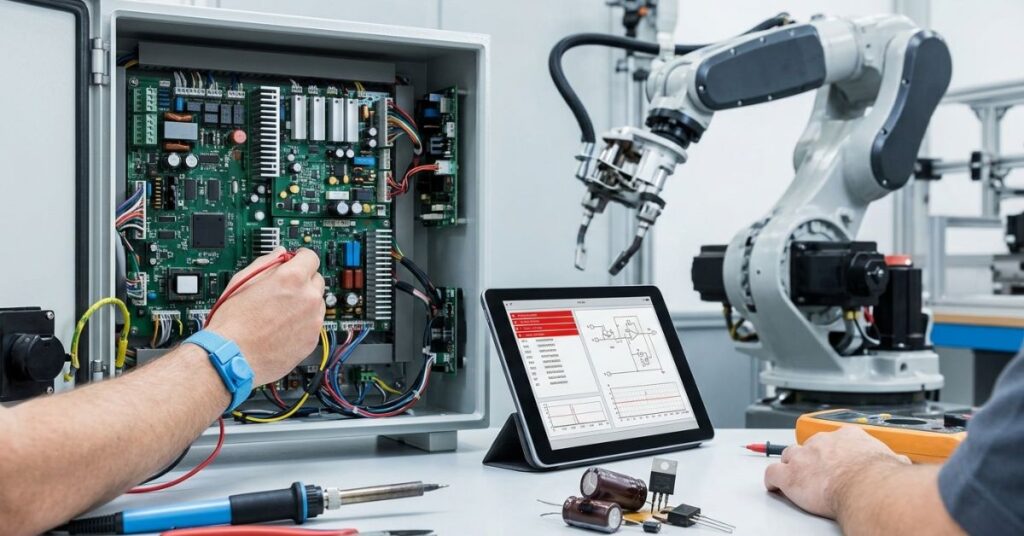
Even well-designed robot control systems encounter performance issues.
Fixing Integral Windup and Overheating Actuators
Integral windup occurs when the integral component accumulates excessive error during saturation conditions.
Common symptoms include:
- Excessive overshoot
- Slow recovery
- Motor overheating
- Oscillatory motion
Solutions include:
- Integral clamping
- Anti-windup logic
- Output saturation limits
- Improved feedforward control
Engineers should also verify actuator sizing because undersized motors frequently contribute to overheating issues.
Eliminating Jitter in High-Speed Position Encoders
Encoder jitter can degrade positioning accuracy and control loop stability.
Common causes include:
- Electrical noise
- Poor grounding
- Loose wiring
- Sampling inconsistencies
- Signal reflections
Recommended solutions:
- Shielded cables
- Differential signaling
- Improved grounding practices
- Hardware filtering
- Encoder quality upgrades
Regular signal analysis with oscilloscopes and logic analyzers helps engineers identify these issues before they affect production.
Conclusion
A robot control system determines far more than simple movement. It governs precision, safety, efficiency, scalability, and long-term operational reliability. Modern robotic controller architecture combines real-time software, deterministic communication protocols, advanced feedback loops, and powerful edge computing platforms to deliver increasingly autonomous behavior.
Organizations that invest in robust control strategies, low-latency communication networks, and rigorous validation methodologies gain significant advantages in productivity and system reliability. Whether you build industrial robotic arms, autonomous mobile robots, or AI-powered automation platforms, mastering control system architecture remains one of the most important factors in achieving predictable and repeatable performance.
Frequently Asked Questions
How does a robot control system work in robotics?
A robot control system works in a continuous loop where it receives commands, processes sensor feedback, computes corrections, and sends signals to actuators. This closed-loop process ensures real-time accuracy, stability, and precise motion control.
Why do industrial robots use closed-loop control?
Closed-loop control uses real-time sensor feedback to continuously correct errors, ensuring high precision, stability, and repeatability in dynamic industrial environments.
What role does ROS 2 play in robotics?
ROS 2 provides a modular and scalable communication framework for robotics, enabling real-time data exchange, multi-robot coordination, and integration with AI, sensors, and industrial systems.
Which communication protocol works best for industrial robots?
EtherCAT is preferred for high-speed, deterministic motion control, while CAN bus is widely used in cost-sensitive and mobile robotic systems due to its simplicity and robustness.
How can engineers reduce robot control latency?
Latency can be reduced by optimizing network architecture, using edge computing, minimizing communication overhead, and ensuring efficient real-time processing in control loops.
What causes encoder jitter in robotic systems?
Encoder jitter is typically caused by electrical noise, poor grounding, wiring instability, or inconsistent sampling rates, all of which affect position accuracy and control stability.

Qasim Ali is a Lead AI Solutions Architect and the founder of TechyPulse, with over 12 years of experience in enterprise digital transformation. Holding an MSc in Computer Science, he specializes in making Artificial Intelligence, Cybersecurity, and Machine Learning accessible and scalable. Qasim is dedicated to decoding complex neural networks into actionable insights for the modern technical landscape.