
Introduction
Modern robots must make decisions in milliseconds. Whether a robotic arm sorts packages on a logistics line or an autonomous drone navigates through rapidly changing environments, perception speed often determines success or failure.
Traditional camera systems struggle when robots move quickly. Motion blur, latency, excessive bandwidth consumption, and poor performance under extreme lighting conditions create bottlenecks that limit autonomous performance.
Instead of capturing entire image frames at fixed intervals, event-based cameras record only pixel-level brightness changes. This approach dramatically reduces latency, eliminates motion blur, and enables robots to react at microsecond speeds.
In this guide, we explore how an EVO camera robot architecture works, why it outperforms conventional vision systems, and how engineering teams deploy event-driven perception pipelines for industrial automation, drone navigation, and autonomous tracking applications.
What Is an EVO Camera Robot?
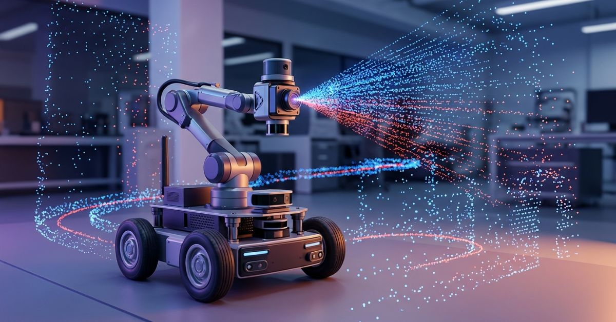
An EVO camera robot combines an event-based vision sensor with visual odometry algorithms, inertial sensors, and robotic control systems to create an ultra-low-latency perception platform.
Unlike conventional cameras that capture complete frames at 30–60 FPS, event-based sensors operate asynchronously. Every pixel independently reports brightness changes the moment they occur.
This architecture allows robots to:
- Detect movement instantly
- Track objects during rapid motion
- Operate in extreme lighting conditions
- Reduce processor workload
- Improve SLAM accuracy
- Support real-time autonomous navigation
The result is a robotic vision system capable of tracking movement at microsecond resolution without suffering from traditional motion blur.
Why Traditional Robotic Cameras Struggle During High-Speed Motion
Most robotic vision systems still rely on CMOS image sensors. While these sensors work well in controlled environments, they encounter major challenges when robots perform rapid maneuvers.
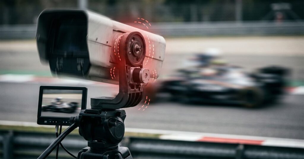
Traditional Frame-Based Capture
Traditional Frame-Based Capture
Frame 1 → 16–33 ms delay → Frame 2
During this delay period:
- Objects move significantly
- Motion blur increases
- Tracking accuracy decreases
- Localization uncertainty grows
As robotic speed increases, these limitations become increasingly severe.
Event-Based Sensor Operation
Brightness Change
↓
Event Stream
Instead of waiting for the next frame, pixels transmit information immediately whenever brightness changes occur.
This approach enables:
- Near-zero latency perception
- Continuous motion tracking
- High dynamic range sensing
- Reduced computational load
Hardware Architecture and the Physics of Latency
Latency directly affects robotic performance. A robot cannot react to information it has not yet received. Traditional cameras create latency because they must expose, read, transmit, and process entire image frames before generating actionable data. Event-based cameras eliminate this bottleneck.
Core Components of an EVO Camera Robot
| Component | Function |
| Event Camera Sensor | Detects asynchronous brightness changes |
| IMU | Measures acceleration and rotation |
| Robot Controller | Executes motion commands |
| Edge Computing Unit | Processes event streams |
| SLAM Engine | Builds environmental maps |
| Sensor Fusion Module | Combines visual and inertial data |
Together, these components create a low-latency perception stack capable of supporting advanced autonomous systems.
Sensor Performance Benchmark
| Performance Metric | Standard CMOS Robotic Camera | EVO Event-Based Sensor Rig |
| Temporal Latency | 10 ms – 30 ms | 1–10 microseconds |
| Dynamic Range | ~60 dB | 130–140 dB |
| Power Consumption | 1.5–2.5 W | ~20 mW |
| Data Bandwidth | 10–30 MB/s | ~100 KB/s |
| Motion Blur Susceptibility | Extremely High | None |
These performance advantages explain why researchers increasingly deploy event-based visual odometry systems in robotics and autonomous navigation applications.
How Event-Based Visual Odometry Works
Visual odometry estimates a robot’s movement by analyzing changes in visual information over time. Traditional systems compare image frames. Event-based systems process brightness transitions instead.

Step 1: Event Generation
Pixels trigger events whenever brightness changes exceed predefined thresholds.
Each event contains:
- Pixel coordinates
- Timestamp
- Polarity information
Step 2: Event Aggregation
The system groups events into spatiotemporal structures that represent environmental features.
Step 3: Motion Estimation
Algorithms estimate robotic ego-motion using feature trajectories derived from event streams.
Step 4: Sensor Fusion
The system combines event data with IMU measurements to improve accuracy.
Step 5: Continuous Localization
The robot continuously updates its position and orientation in six degrees of freedom (6-DoF).
Even during aggressive motion, this process creates highly accurate real-time localization.
Recommended: How Automation and Robotics Are Transforming Modern Business
The TechyPulse 5-Step Calibration Methodology
Successful deployment requires more than advanced hardware. Calibration determines whether the system achieves laboratory-grade precision or operational inconsistency.
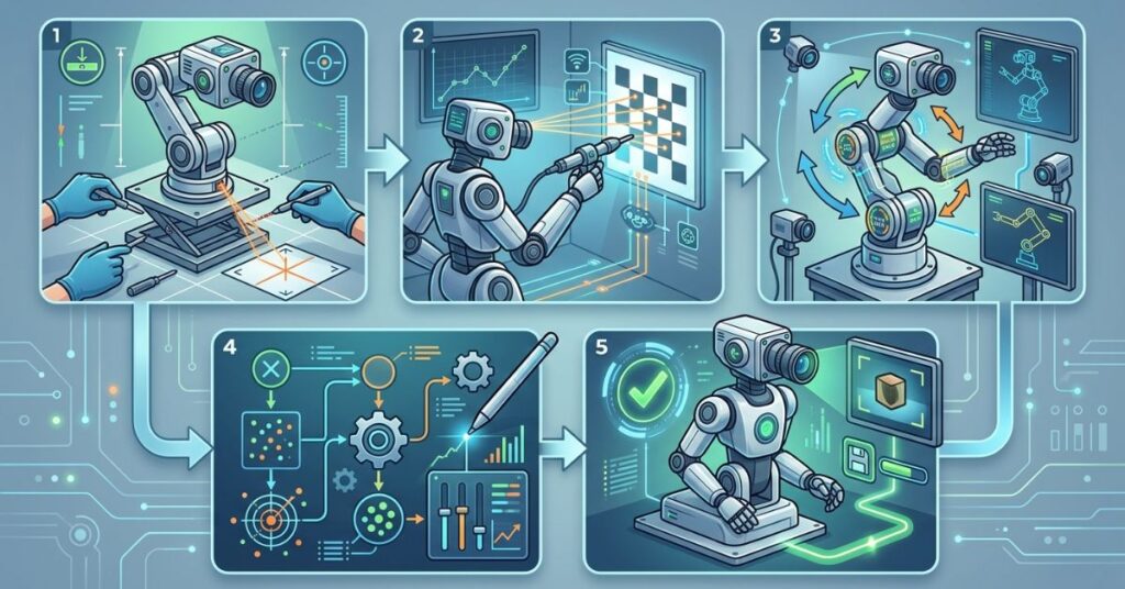
Step 1: Intrinsic Matrix Initialization
Pinhole Alignment
Engineers calibrate the lens using an active LED checkerboard target.
Unlike conventional cameras, event sensors require brightness transitions to generate usable calibration data.
Key objectives include:
- Lens distortion correction
- Principal point estimation
- Focal length determination
Step 2: IMU Time Synchronization
Microsecond Temporal Alignment
The event stream and IMU must share a common time reference.
Engineers use hardware trigger signals to eliminate clock drift and maintain synchronization below five microseconds.
Benefits include:
- Improved sensor fusion
- Reduced drift
- More stable localization
Step 3: Hand-Eye Transformation Matrix Calculation
Kinematic Mapping
Engineers execute a 12-point robotic calibration sequence.
The process computes the transformation matrix:
Tcam-tool
This matrix maps camera coordinates directly to robotic end-effector coordinates.
Accurate mapping ensures precise manipulation and tracking performance.
Step 4: Edge-Map Alignment Testing
Real-Time Tracking Verification
Engineers evaluate tracking performance during high-speed robotic motion.
Testing focuses on:
- 6-DoF tracking stability
- Edge alignment accuracy
- Pose estimation consistency
Most validation sequences exceed 2 m/s movement speeds to replicate real production conditions.
Step 5: Closed-Loop Residual Minimization
Operational Optimization
The final stage analyzes reprojection error and trajectory drift.
If geometric drift exceeds 0.2%, engineers adjust visual-inertial fusion parameters until the system stabilizes.
This optimization phase transforms a functional system into a production-ready autonomous platform.
Event Cameras and High Dynamic Range Vision
Industrial environments rarely provide perfect lighting.

Robots often encounter:
- Reflective surfaces
- Direct sunlight
- Welding sparks
- Warehouse shadows
- Flashing indicators
Traditional sensors struggle under these conditions.
Event-based sensors maintain performance because they respond to brightness changes rather than absolute intensity values.
Example Scenario
A robotic arm moves from a dim warehouse corner at 10 lux into direct sunlight exceeding 10,000 lux.
A conventional camera may:
- Overexpose
- Lose tracking
- Introduce localization errors
An event-based camera continues detecting changes and maintains tracking lock throughout the transition.
This capability makes event-driven vision particularly attractive for industrial automation and autonomous drone navigation.
Enterprise Case Study: High-Speed Sorting Optimization
Real-world performance ultimately determines technology value.
The Challenge
A logistics company experienced a 34% sorting error rate.
Their RGB-D camera system struggled to track parcels moving faster than 1.5 m/s.
Motion blur degraded object localization accuracy and created costly sorting mistakes.
The Solution
Engineers deployed an EVO camera robot tracking pipeline featuring:
- Event-based vision sensors
- Direct photometric edge alignment
- Visual-inertial odometry fusion
- Real-time trajectory estimation
The Outcome
The results exceeded expectations.
| Metric | Before Deployment | After Deployment |
| Sorting Accuracy | 66% | 99.4% |
| Tracking Latency | Milliseconds | Microseconds |
| Processing Speed | Baseline | +62% |
| Motion Blur | Severe | Eliminated |
| Compute Load | High | Significantly Reduced |
The facility improved throughput while reducing operational costs and tracking failures.
Event Cameras for Autonomous Drones
Drone navigation presents some of the most demanding perception challenges in robotics.
Fast rotations, changing illumination, and limited onboard computing resources create significant obstacles.
Event-based visual odometry solves many of these problems.
Key Advantages
Ultra-Fast Response Times
Microsecond-level latency allows drones to react rapidly to environmental changes.
Better Obstacle Avoidance
Event streams capture motion details that conventional cameras often miss.
Reduced Power Consumption
Lower power requirements extend flight duration.
Improved Navigation in Low Light
Event sensors continue operating effectively where frame-based cameras struggle.
Researchers increasingly use DAVIS240c camera sensor integration and continuous-time visual-inertial odometry frameworks to improve autonomous flight performance.
ROS 2 Integration and Real-Time Processing
Most robotics teams build event-based applications using ROS 2.
A typical deployment pipeline includes:
- Install camera drivers
- Configure IMU synchronization
- Build ROS 2 workspace
- Launch sensor nodes
- Initialize SLAM services
- Start trajectory estimation
Recommended Hardware
| Hardware Category | Recommendation |
| Event Sensor | DAVIS240c or equivalent |
| IMU | Industrial-grade MEMS IMU |
| Processor | NVIDIA Jetson or x86 Edge PC |
| Controller | STM32 or ARM-based MCU |
| Communication | Gigabit Ethernet |
This architecture supports robust onboard real-time SLAM processing without excessive compute requirements.
Future Trends in Biologically Inspired Robotic Vision
Nature inspired many event-based vision concepts. The human eye does not process the world as a sequence of discrete frames.
Instead, biological vision continuously reacts to environmental changes.
Researchers continue developing:
- Neuromorphic processors
- Event-driven neural networks
- Self-supervised localization models
- Adaptive robotic perception systems
- Autonomous robotic camera tracking frameworks
These innovations will likely redefine robotic perception over the next decade.
Recommended Multimedia Assets
Visual Diagram 1
Create a wiring schematic showing:
- Event camera sensor
- IMU
- Robot controller
- Edge computer
- Communication bus
Visual Diagram 2
Show a side-by-side comparison:
- Motion-blurred RGB frame
- Event-based reconstructed point cloud
Video Asset 1
Demonstrate robotic tracking under dramatic lighting transitions between 10 lux and 10,000 lux.
Video Asset 2
Provide a ROS 2 installation and deployment walkthrough for developers.
Interactive Simulator
Allow users to modify:
- Robot velocity
- Sensor latency
- Dynamic range
- IMU sampling rate
- Processor bandwidth
Displaying the resulting tracking accuracy helps procurement teams evaluate hardware configurations before deployment.
Frequently Asked Questions
What is an EVO camera robot?
An EVO camera robot combines event-based vision sensors, inertial measurements, and visual odometry algorithms to achieve ultra-fast robotic perception and localization.
Why do event cameras outperform traditional robotic cameras?
Event cameras capture brightness changes asynchronously rather than recording entire frames. This approach eliminates motion blur, reduces latency, and lowers bandwidth requirements.
Can event-based cameras work in low-light environments?
Yes. Event-based sensors maintain strong performance in low-light and high-contrast conditions because they detect brightness changes instead of relying solely on image intensity.
What industries benefit most from event-based visual odometry?
Logistics, aerospace, manufacturing, autonomous vehicles, defense, robotics research, and drone navigation benefit significantly from event-driven perception systems.
Do event cameras require GPU acceleration?
Not always. Their sparse data streams often allow efficient processing on CPUs or low-power edge computing platforms.
Conclusion
Event-based visual odometry represents a major leap forward in robotic perception. While traditional frame-based cameras continue to serve many applications, they struggle to meet the demands of high-speed autonomous systems operating under challenging environmental conditions.
An EVO camera robot architecture addresses these limitations through asynchronous sensing, microsecond-level latency, exceptional dynamic range, and dramatically reduced computational overhead. Organizations that deploy event-driven vision systems gain faster tracking, more accurate localization, better obstacle avoidance, and improved operational efficiency.
As neuromorphic computing and event-based sensor technology continue to mature, these systems will become a foundational component of next-generation robotics, autonomous drones, industrial automation platforms, and intelligent machine perception.
Related AI Articles: Machine Learning Spend Analysis: Smarter Procurement Guide

Qasim Ali is a Lead AI Solutions Architect and the founder of TechyPulse, with over 12 years of experience in enterprise digital transformation. Holding an MSc in Computer Science, he specializes in making Artificial Intelligence, Cybersecurity, and Machine Learning accessible and scalable. Qasim is dedicated to decoding complex neural networks into actionable insights for the modern technical landscape.